Wiring up a full Bank
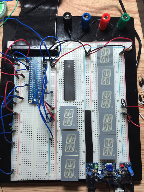
I got one digit to work but I need to prototype the full 8 digits before adding an intelligent front end (that’s later). I place all of my digits on the breadboard and move the MAX6954 to the top so that I can drive it from the Raspberry Pi like I did before. In order to wire my digits I need to note the pin 1 location for all of my digits so I can wire them up correctly.
| Part | Bank | Breadboard Pin |
|---|---|---|
| MAX6954 | 1 | 55 |
| Digit 0 | 1 | 30 |
| Digit 1 | 1 | 19 |
| Digit 2 | 1 | 8 |
| Digit 3 | 2 | 61 |
| Digit 4 | 2 | 50 |
| Digit 5 | 2 | 39 |
| Digit 6 | 2 | 28 |
| Digit 7 | 2 | 17 |
This is shown below where digit 0 is right below the MAX6954 and digit 7 is in bank 3 (of the Breadboard) at the bottom. Sharp eyes will see that the Adjustable breadboard power supply kit - v1.0 is upside down from the previous display. This is because the supply has the positive rail on the outside and the negative rail on the inside. The Adafruit tutuorial works fine as long as you are using their half sized breadboard. Using the full sized breadboard or the large solderless breadboard (like me) you’ll get the same issue. By flipping it I reverse the output sense and it works fine. The electrical tape on part of the breadboard is there so that I can remember to not use those pins for power since they are the input power which in my case is 5 V. That doesn’t go well with 3.3 V!.
Duplicating the Circuit
I rewire the circuit from the previous experiment. The connections between the MAX6954 and the Kingbright display digit require some work since they use different notations for the segments. The pin translation table is shown below. Note that This translation table is only for Digit 0. Most of the signals are the same except for the signals above line 7.
| Line | Display Pin | Display Segment | MAX Segment | MAX Signal | Max Pin |
|---|---|---|---|---|---|
| 1 | 11 | Common Cathode | CC | O0 | 7 |
| 2 | 1 | a | a1 | O2 | 9 |
| 3 | 18 | b | a2 | O3 | 10 |
| 4 | 16 | c | b | O4 | 11 |
| 5 | 13 | d | c | O5 | 12 |
| 6 | 10 | e | d1 | O6 | 13 |
| 7 | 9 | f | d2 | O7 | 14 |
| 8 | 8 | g | e | O8 | 15 |
| 9 | 4 | h | f | O9 | 26 |
| 10 | 3 | k | h | O12 | 29 |
| 11 | 2 | m | i | O13 | 30 |
| 12 | 17 | n | j | O14 | 31 |
| 13 | 15 | p | g2 | O11 | 28 |
| 14 | 14 | r | k | O15 | 32 |
| 15 | 6 | s | l | O16 | 33 |
| 16 | 7 | t | m | O17 | 34 |
| 17 | 5 | u | g1 | O10 | 27 |
| 18 | 12 | dp | dp | O18 | 35 |
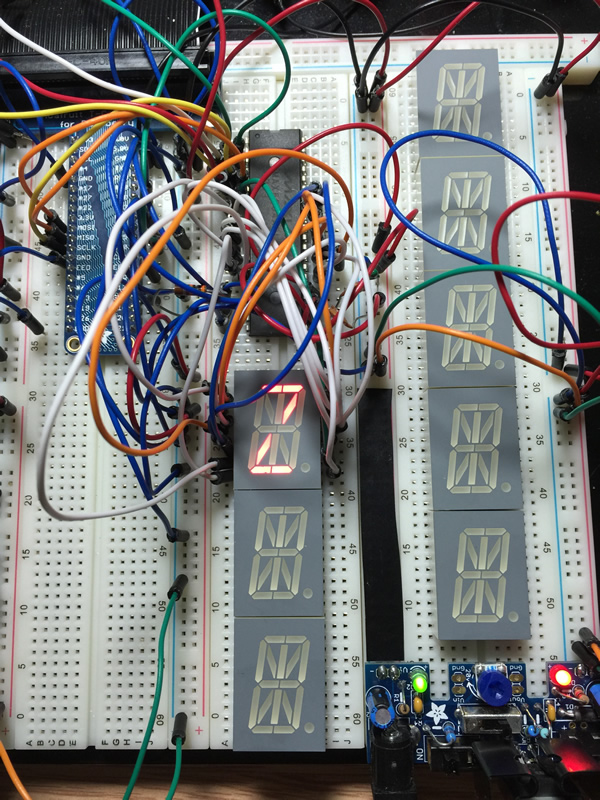
I initially had the Raspberry Pi driving the board but I want to use the regulated power supply to do so. I disconnected the Raspberry Pi from driving the board and then I connected the regulated power supply. It would work for a while but then it would stop. The fix was simply connecting more power and ground lines from where the supply was driving the rails. I was starved for current with my thin wires. Once I did that it worked fine and I could run my letters in sequence.
The final wired setup for a single digit is shown below.
What’s Next?
Now that I’ve got the circuit moved and working correctly using the new power supply I can wire up the rest of the digits and test them.