Finishing the Power Regulated Power Supply
I finished up the Adjustable breadboard power supply kit - v1.0 by following their excellent directions. One word of warning though. The power supply kit generates two different voltages on the two sets of output pins. The left side is the selected voltage range which can be 3.3 V, 5 V, or a voltage set by the pot in the center of the board. The right side is the input voltage minus a 0.2 V (approximate) drop. Take a look at the installed board on my setup.
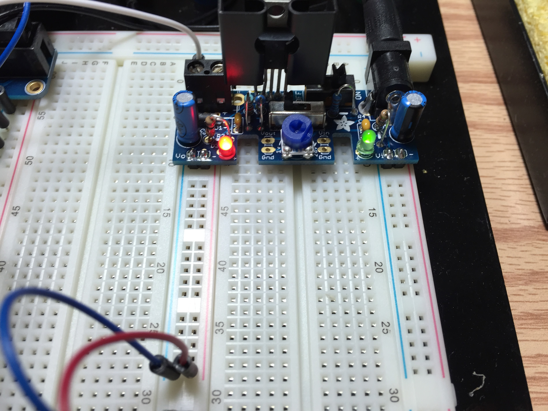
The left rails (with the jumpers between segments) will contain 3.3 V. The right side (with no jumpers between rail segments) is the input voltage of 5 V which comes from the wall wart I bought from AdaFruit. BTW, it took a bit of practice before my solder joints looked good again! My first 5 or so joints were terrible but by the end they were the shiny cones that they are supposed to be.
Time to Pivot
While investigating my multisegment LED chips I came across an even better driver chip made by Maxim no less! The MAX6954 was made specifically to drive banks of multisegment LEDs with 8 multisegment LEDs per chip! This means I’d only need two chips per bank or four chips for my whole display. This is way better than my approach to use switched transistors and the MAX6957.
I rushed over to Mouser and bought some more multisegment LED chips and my new best friend, the MAX6954!
What’s Next?
I’ve ordered my new chips and multisegment LEDs so I’ll wait for them to show up and then I can prototype my new approach to the display.